Contents
Introduction
Understanding Kirchhoff laws is essential to solve for voltages and currents in a circuit. There are two laws: Kirchhoff Voltage Law and Current Law (abbreviated to KVL and KCL respectively). Instead of thinking KVL and KCL as a mathematical concept, think of it as a tool for you to analyze circuits. After all, a circuit tells you nothing but voltages and currents. Since all electronics components have their own behaviour of voltages and currents, it is absolutely crucial that one knows how to use KVL and KCL to understand how a particular circuit operates.
Before delving into Kirchhoff laws, we must understand what a circuit node and loops are. A circuit node is a common point for connecting electronic components. A node connects a component’s terminal to another just like a physical wire. For an example, the connection between a battery and its load is a node. A node at any given time can only have one voltage value.
A circuit loop is a loop from, lets say node A to node B to node C and finally ending back at node A. It must be emphasized that a loop must not have any breaks (electric charge can flow continuously)
By the end of this tutorial, you shall be able to use Kirchoff’s laws to solve currents and voltages of a circuit.
Definition
KVL states that for a given loop in a circuit, the sum of voltages must be equal to zero. On the other hand, KCL states that for a given node in a circuit, equal currents enter and leave that node. These concepts will be made clear with examples shortly. Derivation of these two statements are beyond the scope of this article.
Example: Resistor Circuit

Suppose that we are given a circuit in Figure 1. How do we solve the currents \(I_1\) and \(I_2\)? By knowing these currents we can compute the voltage drop of every resistor. Note that \(I_3\) is a dependent variable and therefore there are only two unknowns in this problem. Also, it is assumed that the values of \(V_1\),\(R_1\),\(R_2\) and \(R_3\) are known.
Step 1 : Label voltage polarities and currents
First, guess the direction of currents \(I_1\), \(I_2\) and \(I_3\) at node 1. I indicated them with arrows. This will determine the voltage polarity of the resistors. The positive terminal of a resistor is where current enters and the negative terminal is where the current exits.
It does not matter which direction you choose for the currents(it exits or leaves node 1). For an example, based on my labels in Figure 1, if the value of \(I_1\) is positive, then current enters node 1. However, if the value of \(I_1\) is found to be negative in our final calculation, this means that \(I_1\) is opposite the initial guess and actually exits node 1 instead of entering.
Ensure consistency in using the voltage polarities and current direction to obtain correct results.
Step 2: Use Kirchoff’s Current Law (KCL)
You have already done this in step 1. This step shall be used later to compute \(I_3\).
By observing the direction of currents at node 1, \(I_1\) enters node 1, while \(I_2\) and \(I_3\) leaves node 1. Hence
\[I_1=I_2+I_3\]
Step 3: Use Kirchoff’s Voltage Law (KVL)
The circuit in Figure 1 has two loops. To use KVL on loop 1, we follow the direction of the loop which is clockwise and taking the ground node as the initial point. The loop first meets the negative terminal of voltage source \(V_1\), then it meets the positive terminal of \(R_1\), and finally it meets the positive terminal of \(R_2\). We sum up these voltages(can be positive or negative, depending on the polarity) and set the right-hand side to zero. Recall that the voltage across a resistor is \(V=IR\)
Loop 1:
\[-V_1+V_{R1}+V_{R2}=0\]
\[-V_1 +I_1R_1+I_3R_2=0\]
\begin{equation}-V_1 +I_1R_1+(I_1-I_2)R_2=0\tag{1}\end{equation}
We now have the first equation, but we cannot solve it yet because there are two unknowns. We need another equation which is obtained by using the same process on the second loop.
Loop 2:
In loop 2, there are only two components, \(R_2\) and\(R_3\) Following the direction of the loop and using the ground node as our initial point, the loop meets the negative terminal of\(R_2\) and then the positive terminal of\(R_3\). We sum up these voltages and obtain
\[-V_{R2} + V_{R3}=0\]
\[-I_3R_2 +I_2R_3=0\]
\begin{equation}-(I_1-I_2)R_2 +I_2R_3=0\tag{2}\end{equation}
Now that we have two equations \((1)\) and \((2)\), we can solve the currents \(I_1\) and \(I_2\).
\[I_1(R_1+R_2)-I_2R_2=V_1\]
\[I_1(-R_2)+I_2(R_3+R_2)=0\]
You can plug in these values into a scientific calculator linear equation solver to get the results. There is no need for manually solving Cramer’s rule or substitution here.
Simulation Example
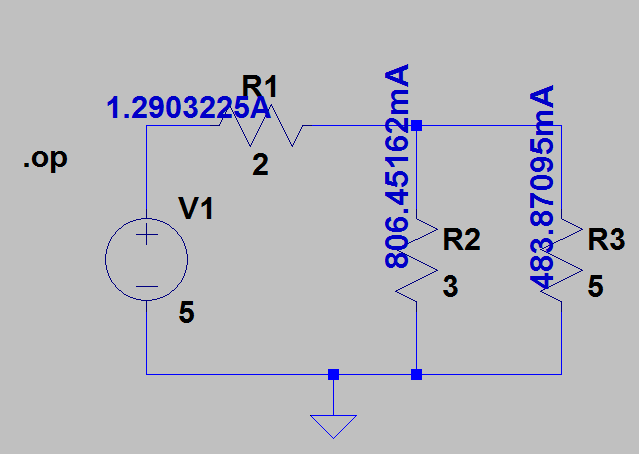
Let \(V_1 = 5, R_1=2,R_2=3,R_3=5\). Using the two unknown linear equation we derived, we obtain the results \(I_1=1.290 A\) and \(I_2=0.483 A\). This is verified by the simulation using LTspice. The spice “.op” directive is invoked to tell the simulator to only compute the operating points or at DC conditions
Conclusion
KVL states that the sum of voltages in a closed path network or a loop must be equal to zero. Care must be taken on the polarity of the components. As for KCL, equal currents enter and leave.
To check if your answer is correct, simply plug into the loop equations and see if the voltages add up to zero, and if equal currents leave and exit a node. If they do not add up, your calculations are most probably wrong.