In this article, we will derive mathematically on how to obtain the equivalent resistors in series or parallel. By simplifying resistors, you can perform circuit analysis quicker. We will also explore some applications of connecting resistors in series or parallel.
Series Resistors
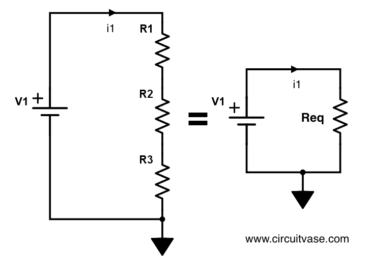
Consider the left side resistor series circuit in Figure 1. The current flowing through \(R_1\), \(R_2\) and \(R_3\) are all equal to \(I_1\). Where else can current \(I_1\) flow? Also, using Kirchoff’s voltage law the sum of voltages of \(R_1\), \(R_2\) and \(R_3\) must be equal to \(V_1\). Writing this in equations yield
\[V_1=I_1R_1+I_1R_2+I_1R_3\]
\[V_1=I_1(R_1+R_2+R_3)\]
\[V_1=I_1R_{total}\]
\[R_{total}=R_1+R_2+R_3\]
Thus to obtain the equivalent resistance in series, \(R_{total}\), simply add them up.
One such typical application of using a resistor in series is to modulate the source voltage by dividing them. It is easier to change the resistance instead of voltage for your application since most voltage sources are fixed, i.e. your 9V battery. Can you find a 5.7 V battery in the market? Probably not. But you can certainly use resistors if you need such voltage.
Voltage Divider

The voltages V1,V2 and V3 to ground are
\[V_1=V_1\frac{R_1+R_2+R_3}{R_1+R_2+R_3}\]
\[V_2=V_1\frac{R_2+R_3}{R_1+R_2+R_3}\]
\[V_3=V_1\frac{R_3}{R_1+R_2+R_3}\]
The voltage drop across a resistor’s terminals instead of straight to ground are
\[V_{R1}=V_1\frac{R_1}{R_{eq}}\]
\[V_{R2}=V_1\frac{R_2}{R_{eq}}\]
\[V_{R3}=V_1\frac{R_3}{R_{eq}}\]
Or generally,
\[\boxed{V_{R_n}=V_{source}\frac{R_n}{R_{eq}}}\]
Parallel Resistors

For a parallel configuration of resistors, the voltage is same across all resistors. But the current is being divided. Using Kirchoff’s Current law, we obtain
\[I_1=I_5+I_6+I_7\]
To find the equivalent resistance, we substitute \(I=\frac{V}{R}\)
\[\frac{V_1}{R_{eq}}=\frac{V_1}{R_5}+\frac{V_1}{R_6}+\frac{V_1}{R_7}\]
\[\frac{1}{R_{eq}}=\frac{1}{R_5}+\frac{1}{R_6}+\frac{1}{R_7}\]
It is more difficult to work in fractions for the parallel circuit case. Instead, use conductance G in place of resistance. The relationship between resistance and conductance is \(G=\frac{1}{R}\).
\[G_{eq}=G_5+G_6+G_7\]
Therefore, the equivalent conductance in a parallel configuration is the sum of each individual conductance. To obtain the equivalent resistance, take the reciprocal of conductance
\[R_{eq}=\frac{1}{G_{eq}}\]
Current Divider
A parallel resistor configuration divides the current according to conductance. A resistor with higher conductance or lower resistance will have more current flowing through it. We seek to find the relation between the total current \(I_1\) and the individual currents \(I_5\),\(I_6\),\(I_7\). Using Figure 3, Let
\[I_1=I_5+I_6+I_7\]
The voltage across all resistors is the same, it follows that
\[V_1=I_1R_{eq}=I_5R_5=I_6R_6=I_7R_7\]
Expressing in terms of conductance,
\[I_1=V_1G_{eq}\]
Solving for \(I_5\) only,
\[V_1=I_1R_{eq}=I_5R_5\]
Rearranging \(I_5\) to the left hand side,
\[I_5=I_1\frac{R_{eq}}{R_5}\]
Generally, for a current divider circuit, the current \(I_n\) at branch \(n\) is
\[\boxed{I_n=I_{source}\frac{R_{eq}}{R_n}}\]
where \(I_{source}\) is the total current before being divided.
Conclusion
A series resistor circuit divides the voltage, while a parallel resistor circuit divides the current.