Introduction
A resistor is a two terminal electronic device which limits the flow of electric charge or current in a circuit. It is made up of poorly conducting materials. Depending on application, resistors come in different shapes and sizes. Usually the bigger the resistor, the larger the current it can handle. Too much current flowing in a small resistor will cause it to burn.
Have you ever wondered what happens if you connect the positive and negative terminals of a battery with a wire? The battery will heat up because of excessive current flow, and will most likely cause it to catch fire. A resistor prevent such situations from occurring by “resisting” current flow. A suitable analogy would be a rotating door limiting the amount of people “flowing” or entering a building. It creates “resistance” for people to walk through the entrance to ensure order and prevent chaos.
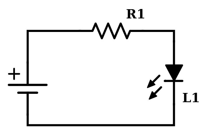
Here is more practical example. Consider the circuit in Figure 1. We all know we can light up an LED by connecting the positive terminal of the LED to the positive terminal of the battery, and the negative terminal of the LED to the negative terminal of the battery. But if you don’t insert a resistor in series between them, and if the current generated is more that the maximum operating current of the LED, it will be damaged.
Resistor properties
The resistance of any conductor can be modeled as
\[R=\frac{\rho l}{A}\]
where \(\rho\) is the resistivity (\(\frac{\Omega}{m}\)) of the material which makes up the conductor, \(l\) is the length and \(A\) is the surface area of the conductor. Note that the longer the physical length of a conductor, the larger the resistance. Therefore long wires exhibit more resistance than shorter wires. The larger the surface area \(A\) , the smaller the resistance. This is because more charge can flow in the material and therefore larger current, just like a five lane highway can allow more cars to drive than a two lane highway.
Ohm’s Law
The next step is understanding what a resistor do in a circuit mathematically. It turns out that the voltage is proportional to the current in a conductor, and the proportionality constant is equal to the resistance of the conductor. Ohm’s law can be stated mathematically as
\[V=IR\]
So, what kind of application do we need to use Ohm’s law? Rearranging \(I\) to be on the left hand side of the equation,
\[I=\frac{V}{R}\]
The current \(I\) in inversely proportional to \(R\), therefore higher resistance creates smaller current at the same voltage \(V\). Ohm’s law can be used to determine resistance values for a given voltage in order to generate a safe operating current depending on application. Looking back at Figure 1, if you need to design such circuits, you would already know your voltage and the nominal operating current of the LED from the datasheet. Plug into the formula \(R=\frac{V}{I}\) and pick a resistor close to that value in your circuit. Suppose that you have a 3.3 V voltage source, and the operating current of your LED is 10mA (you can get this number from the datasheet), the resistor you should use is \(\frac{3.3V}{10mA}=330\Omega\)
Power
The instantaneous power is the multiple of voltage and current:
\[P=VI\]
Use Ohm’s law to compute the power dissipated from a resistor. Substitute \(V=IR\) into \(P=VI\)
\[P=VI=(IR)I=I^2R\]
Or in terms of voltage:
\[P=VI=V\frac{V}{R}=\frac{V^2}{R}\]
Conclusion
I have barely touched the usage of resistors in electronics. There are many other applications for resistors such as voltage divider circuits, biasing in transistors, impedance matching etc. Not to mention that even wires too have resistance and sometimes need to be taken account into calculations. The next step would be understanding how to compute the equivalent resistance of series and parallel resistors.